The development of a smart, wireless temperature control system for enclosed spaces involved the utilization of several key components. Central to this design was the integration of the Atmega16 microcontroller, which provided the necessary computational capabilities for data processing and system control. The HMT&R transmitter and receiver modules were incorporated to facilitate wireless communication between system components, ensuring efficient and reliable data transmission. Additionally, the LM35 temperature sensor was included to accurately monitor and measure temperature levels within the closed environment. The combination of these elements enabled the creation of an intelligent and adaptive temperature control system capable of maintaining optimal conditions within the enclosed space, ultimately showcasing the potential of integrating advanced technologies for enhanced environmental monitoring and control.
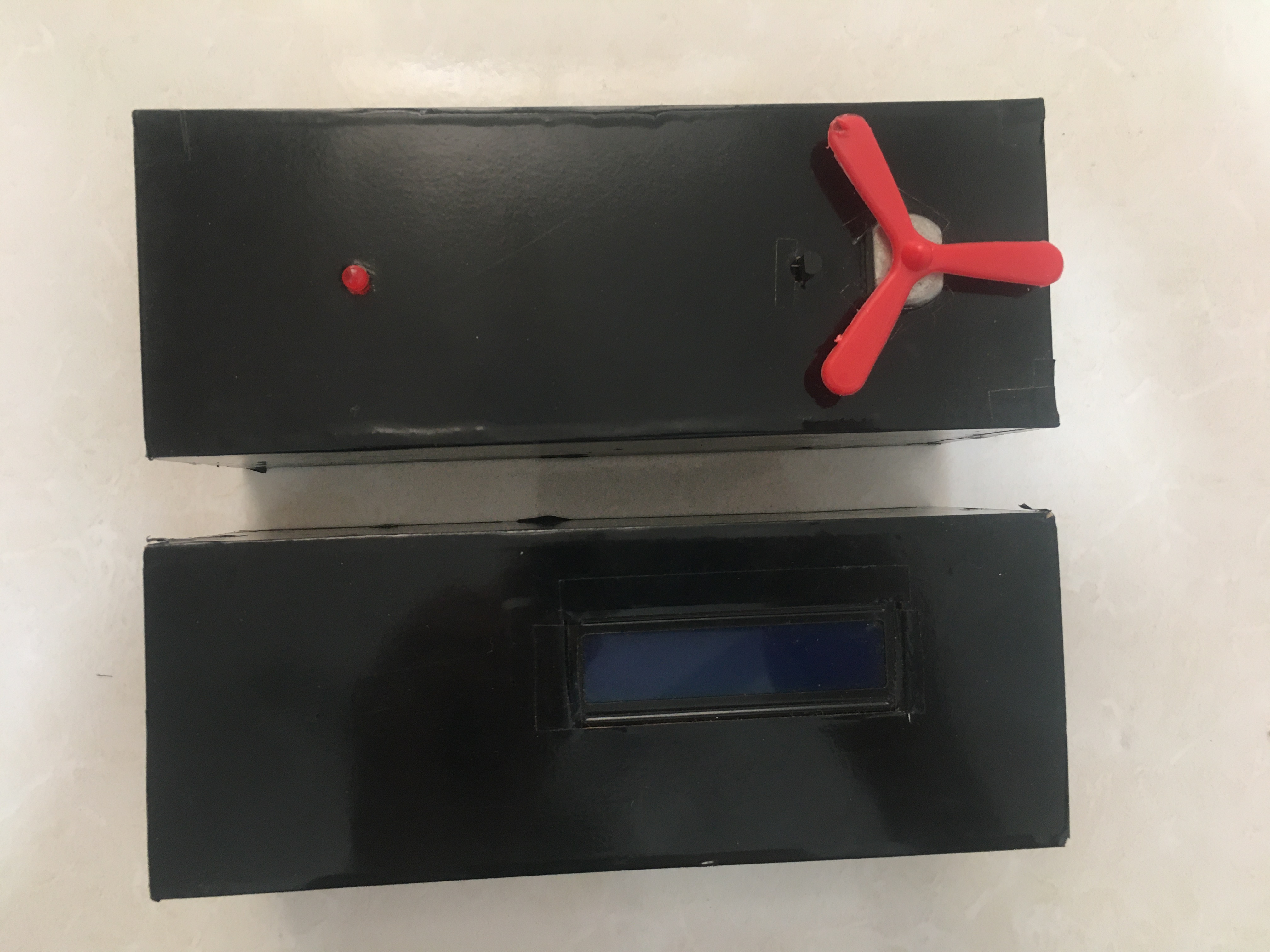
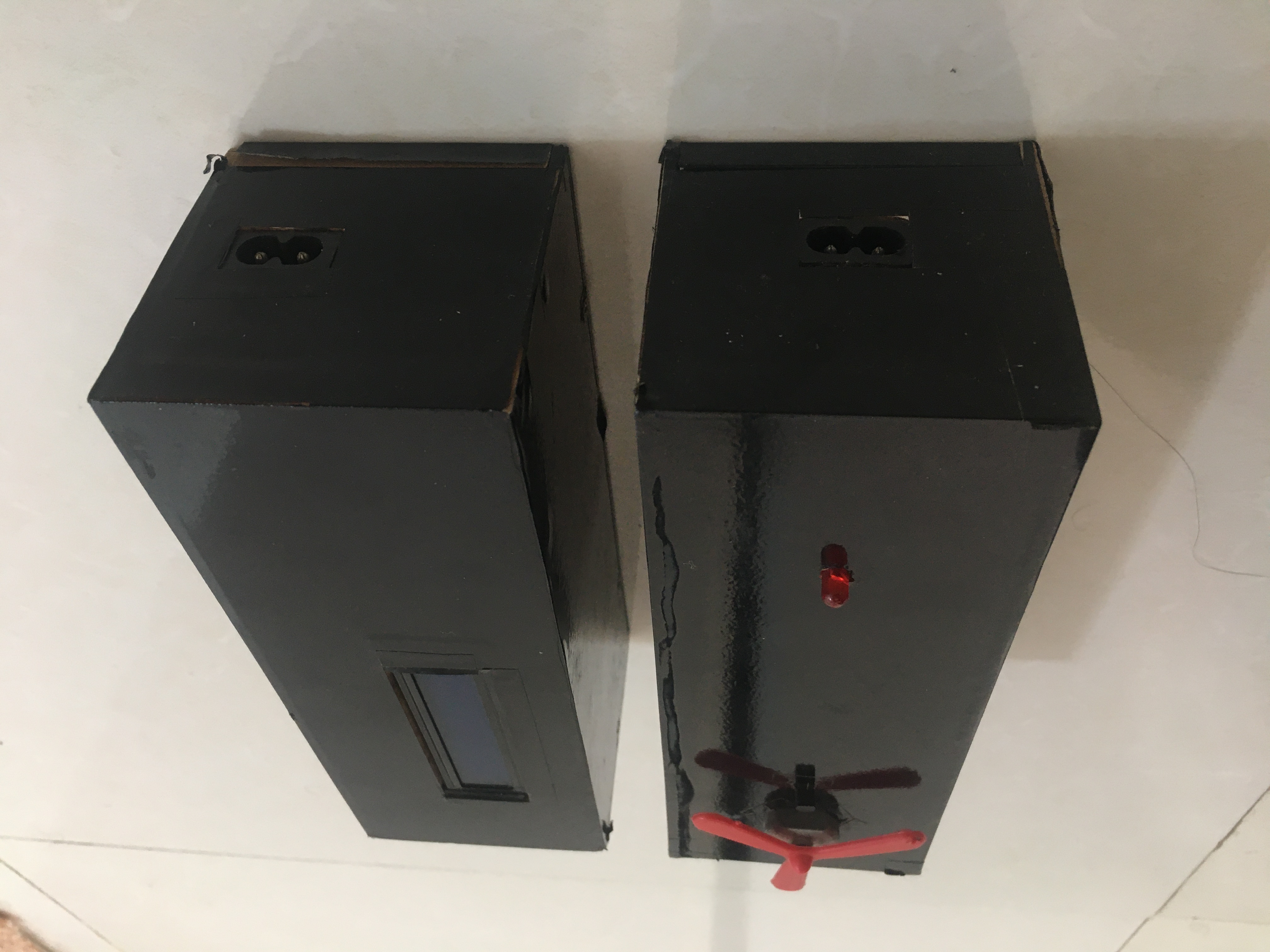
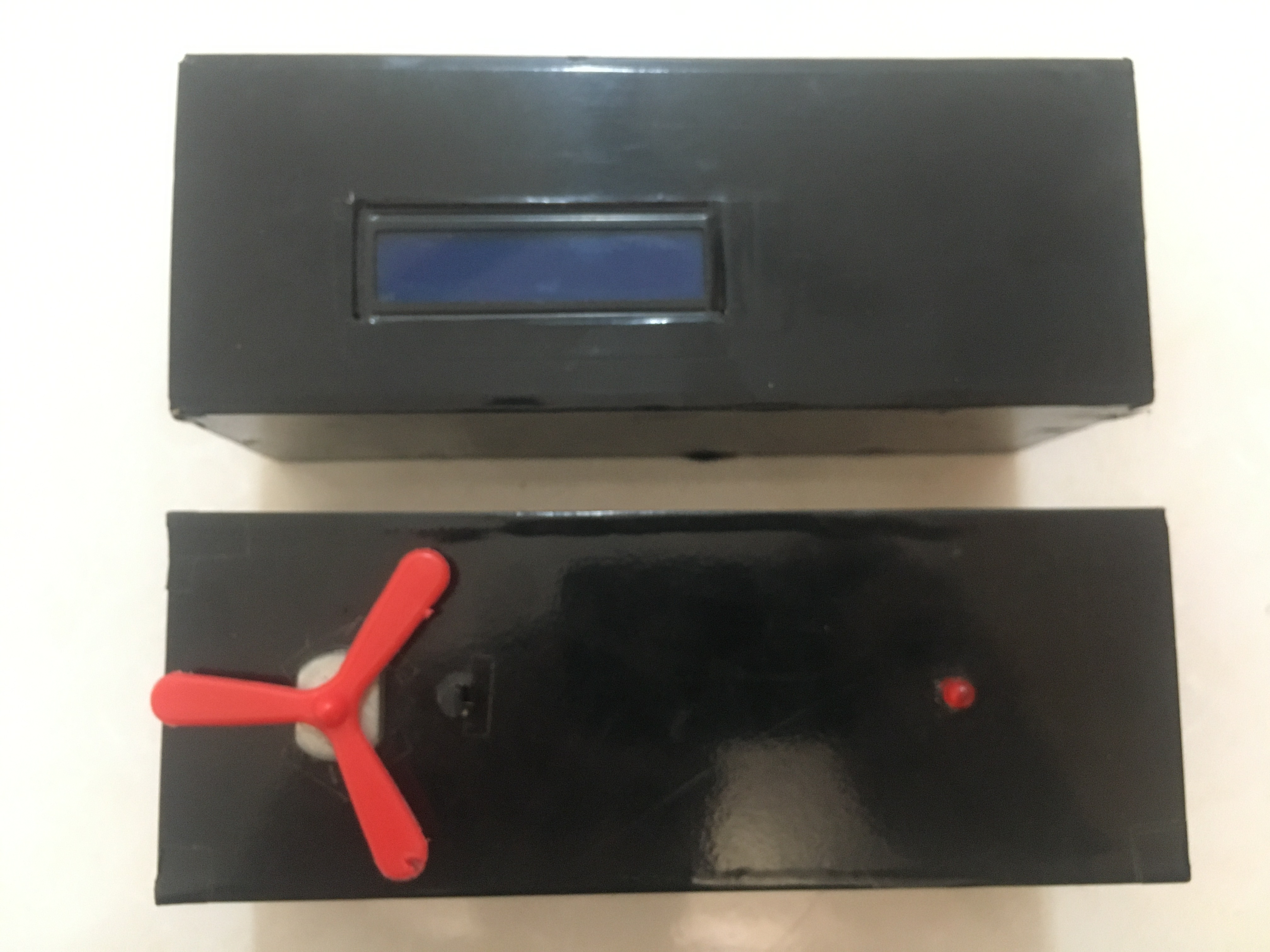
The designed device consists of two parts: transmitter and receiver.
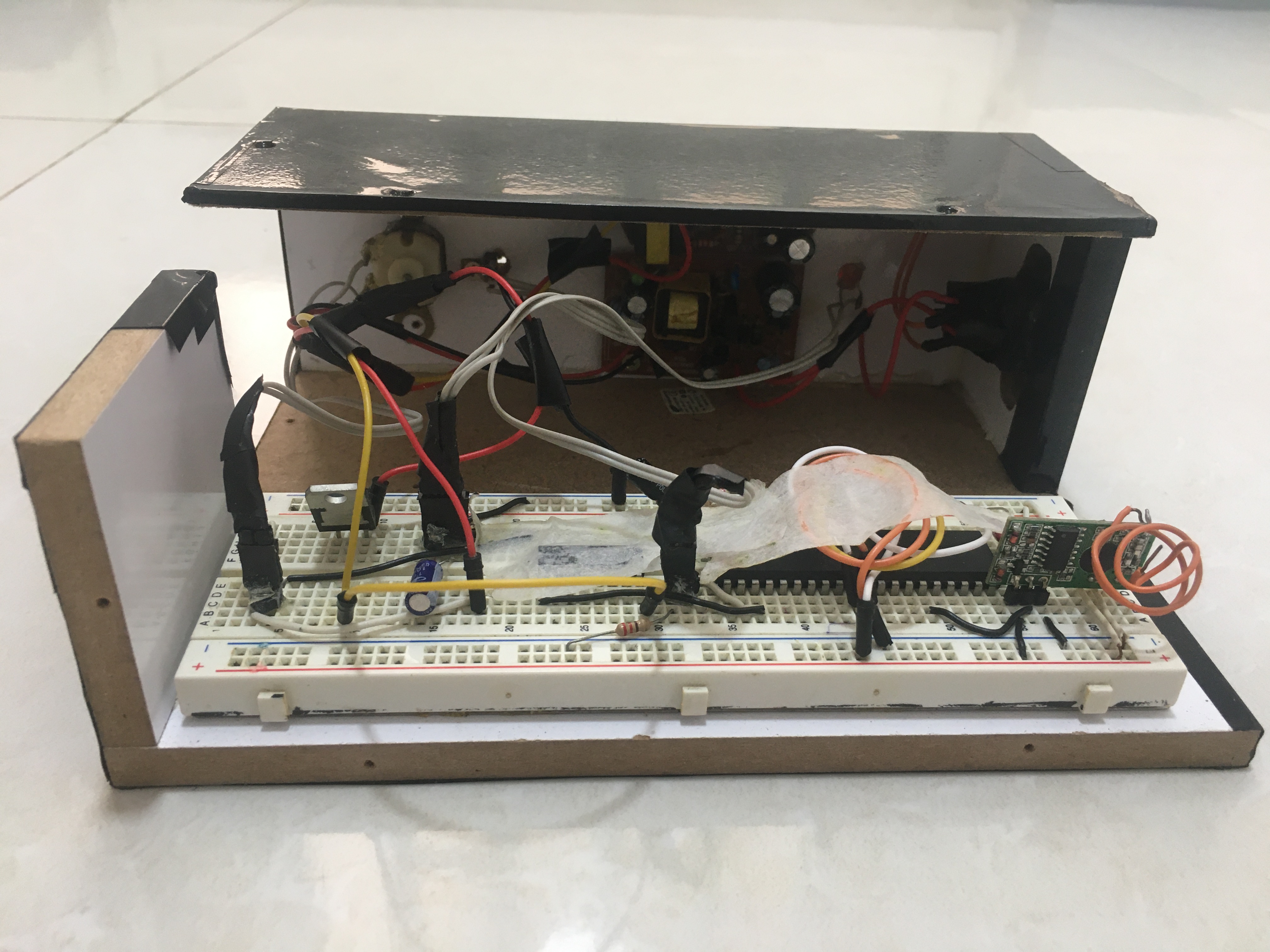
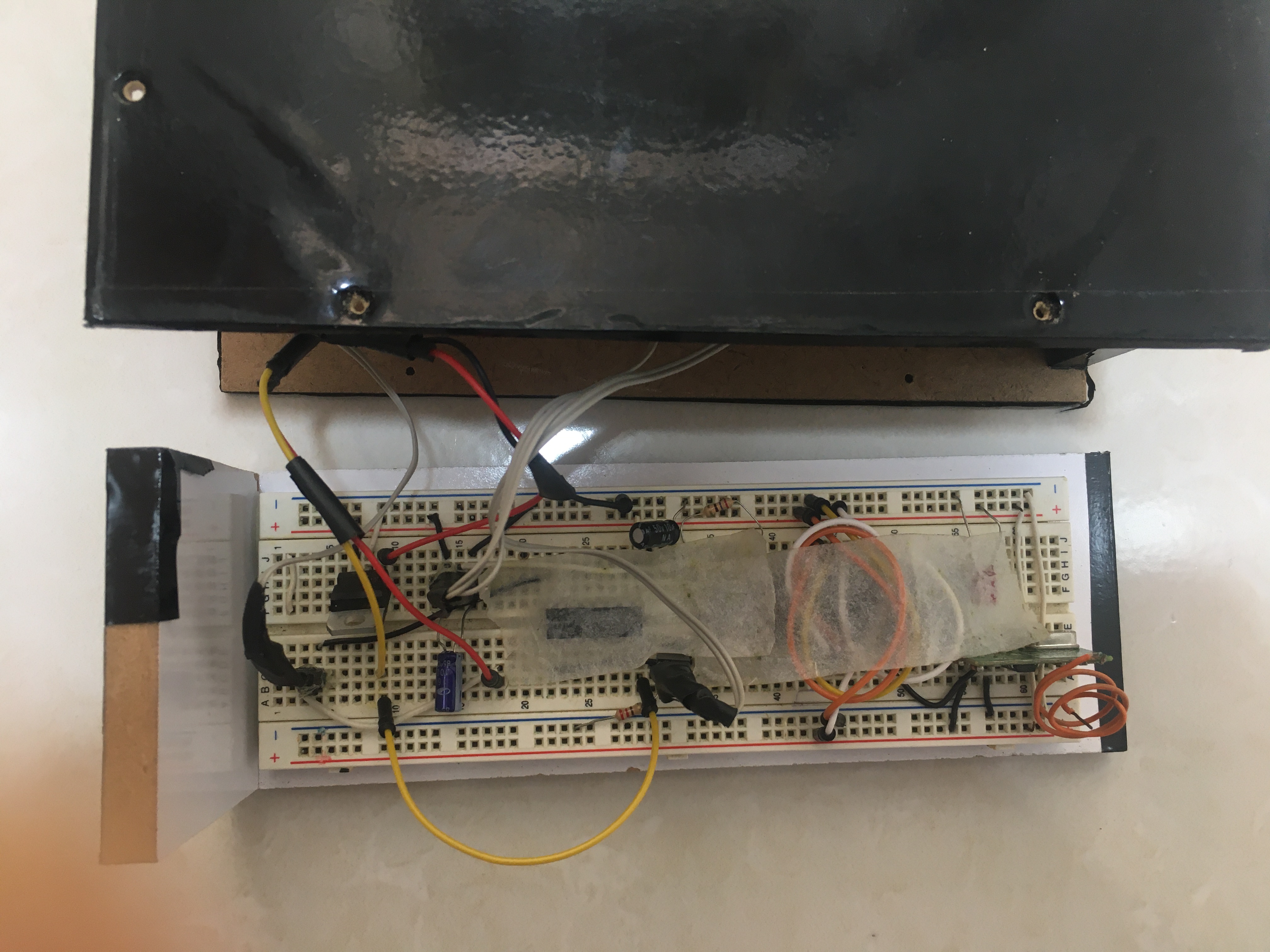
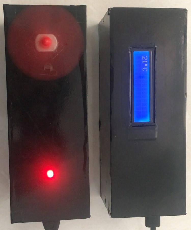
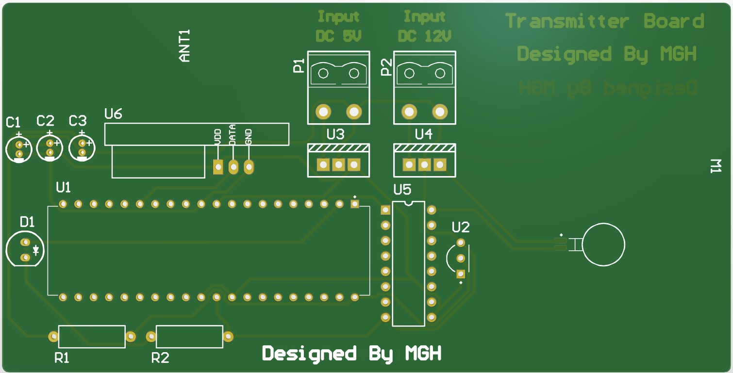
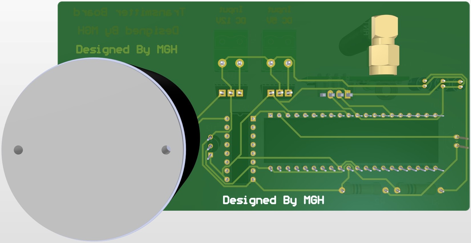
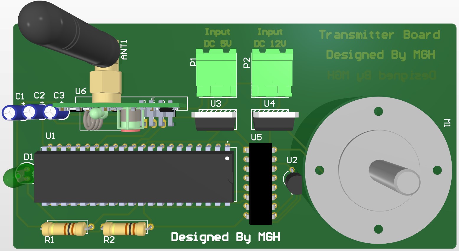
The transmitter part is placed in a closed environment such as a room, and its task is to continuously measure the temperature of the environment and send it to the receiver part. A cooling device such as an armature is also placed in the transmitter section, whose rotation speed can be controlled. There is also an LED in the transmitter section that lights up when the room temperature is favorable (below 20 degrees Celsius). It should be noted that the rotation speed of the armature increases or decreases with the increase or decrease of the room temperature, respectively. The elements used in the transmitter section are: Microcontroller AVR atmega16 to process information, Module LM35 to measure ambient temperature, Module HMT to send information to the receiver, armature for cooling, and warning LED, L298 IC in order to adjust the rotation speed of the armature.
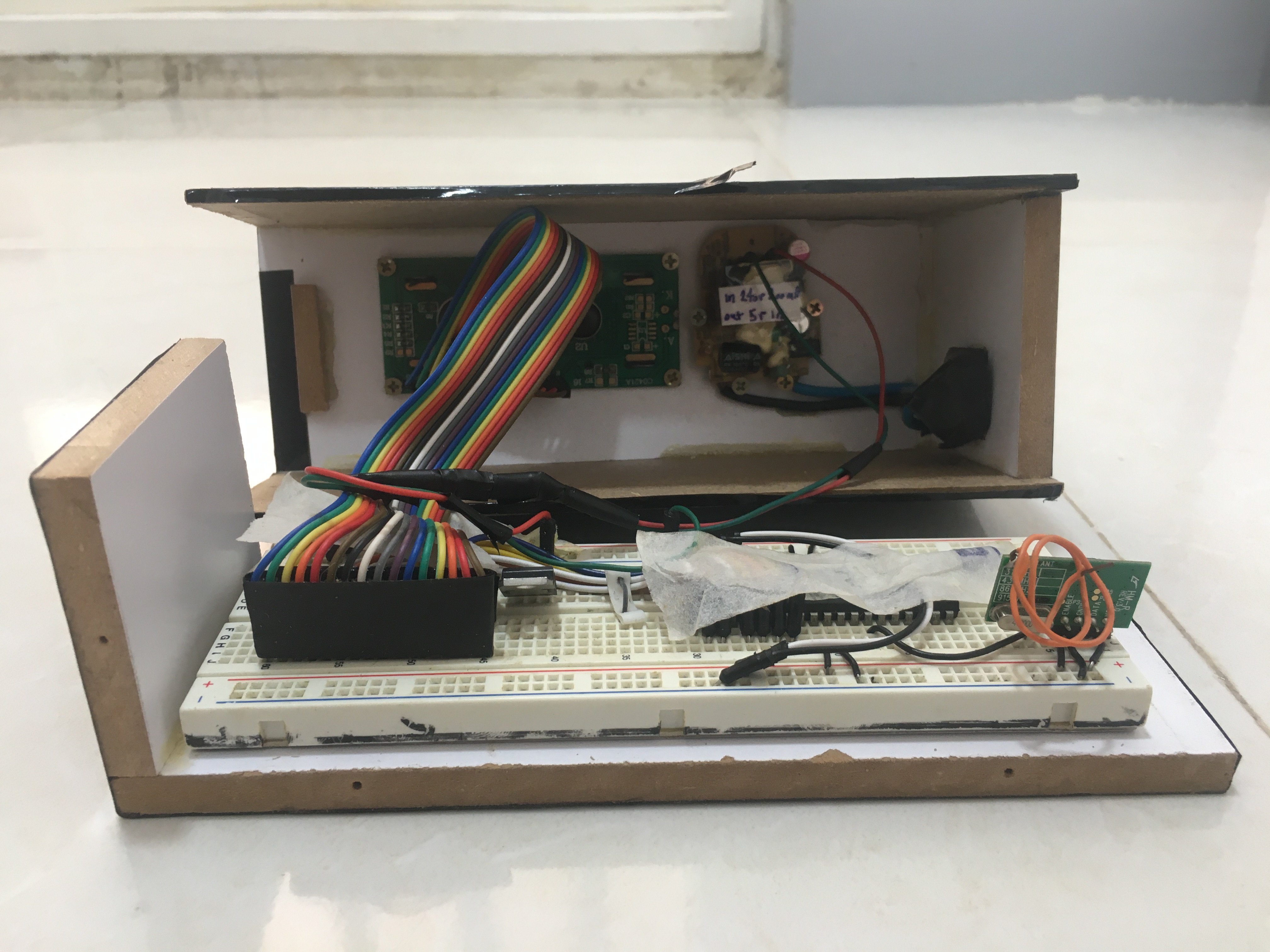
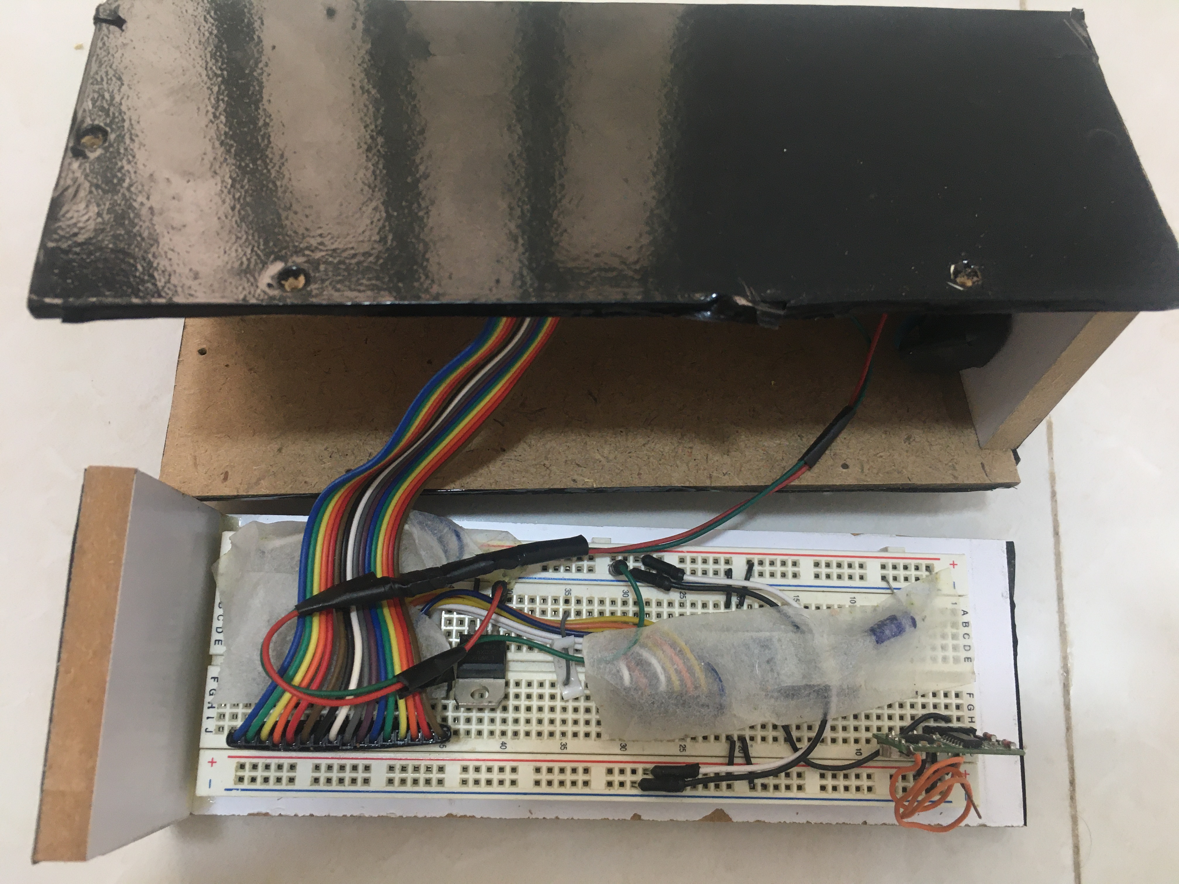
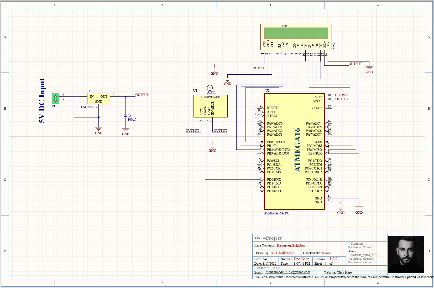
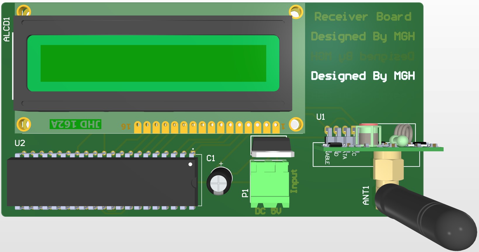
The receiving part is placed in the controller room and has the task of continuously showing the temperature. The elements used in the receiver section are: Microcontroller AVR atmega16 to process information, LCD module to display temperature, and Module HMR to receive information from the transmitter.
The codes of the transmitter and receiver microcontrollers are written in C++ language and programmed on them, which can be seen below:
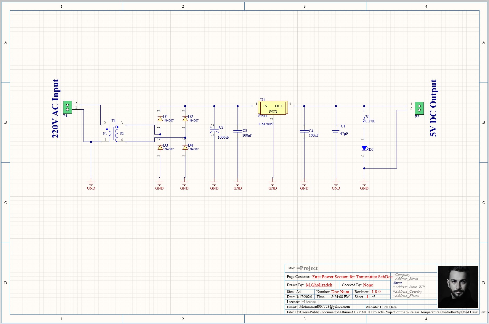
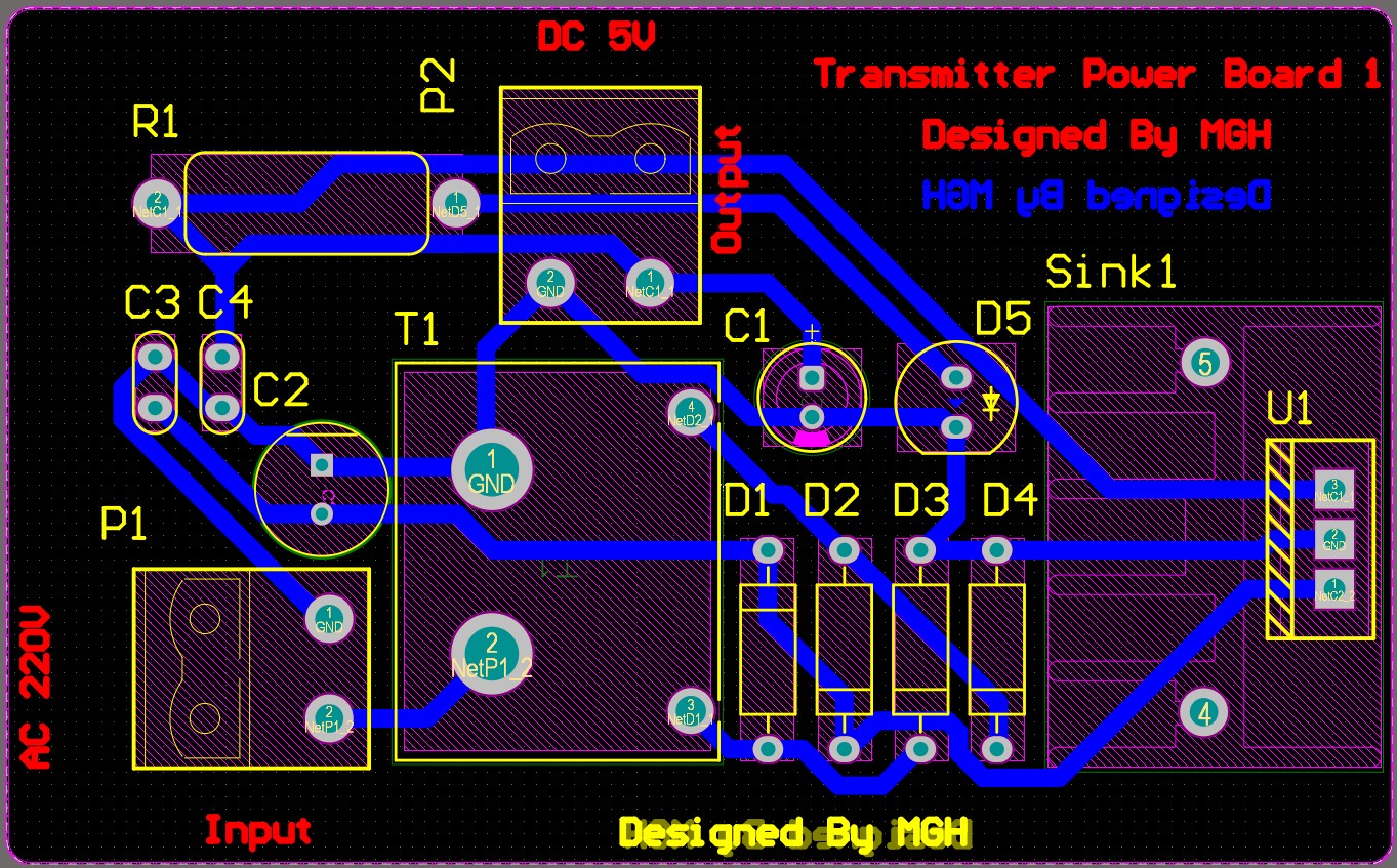
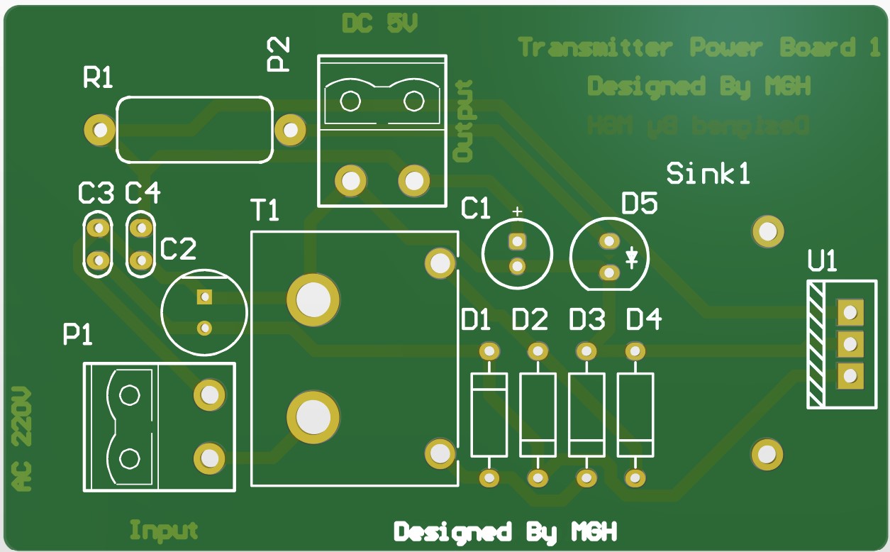
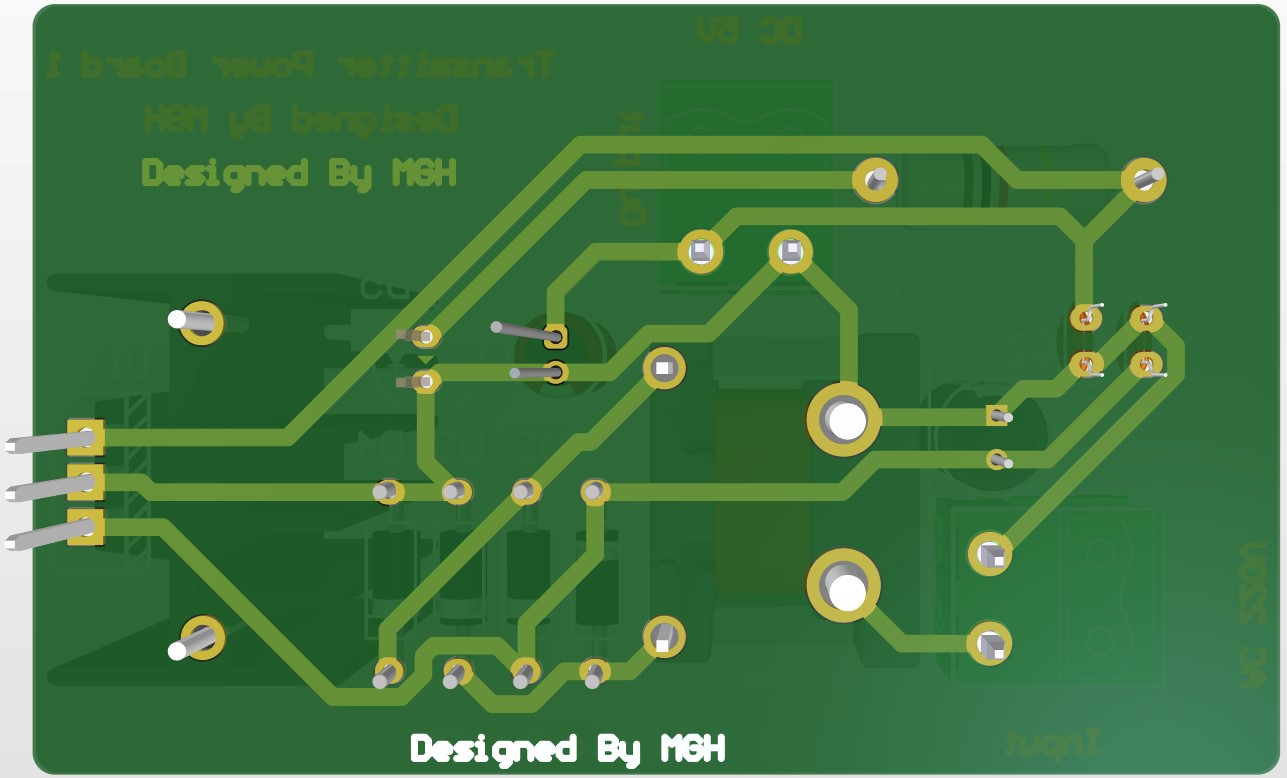
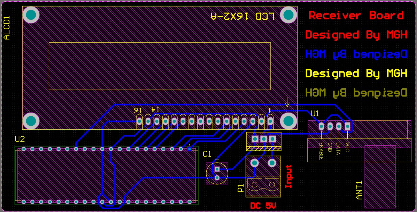
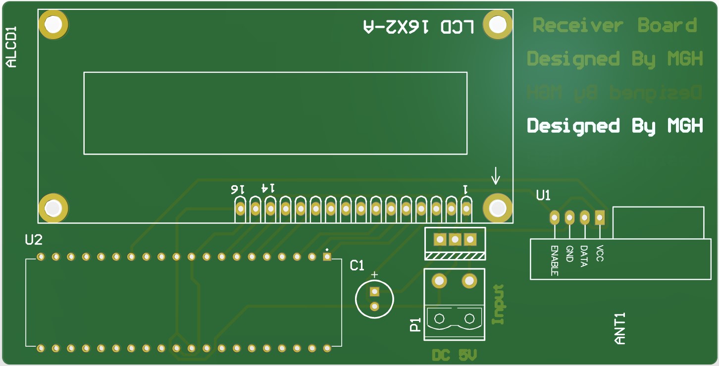
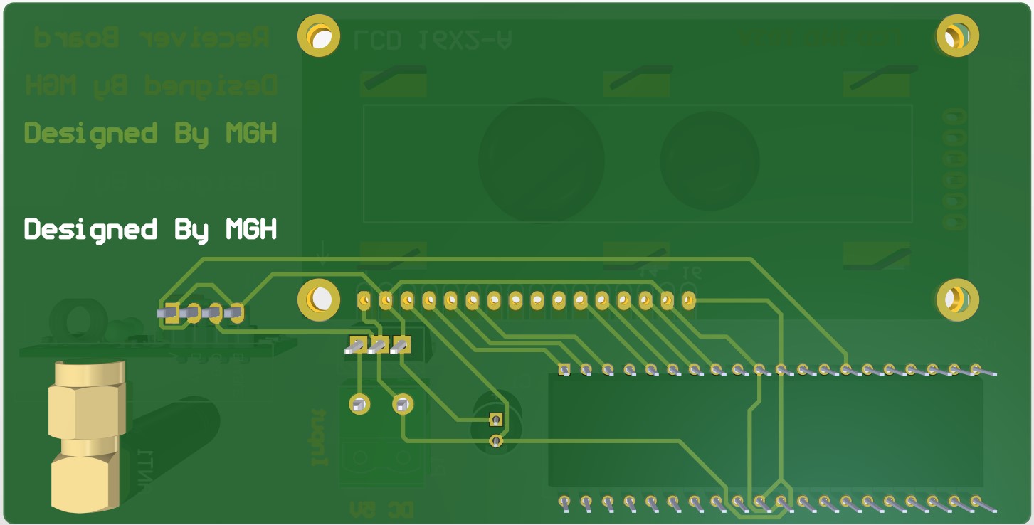
The proposed system was designed and simulated using both Altium Designer and Proteus software. The complete schematic diagrams and PCB layouts were developed in Altium Designer, while system functionality and performance were verified through simulation in Proteus. The design and simulation results are presented below:
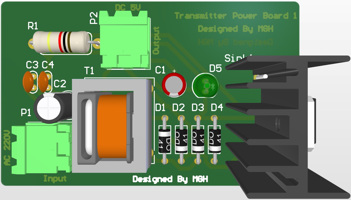
The BOM of the First Transmitter Power Supply Section can be downloaded by clicking here
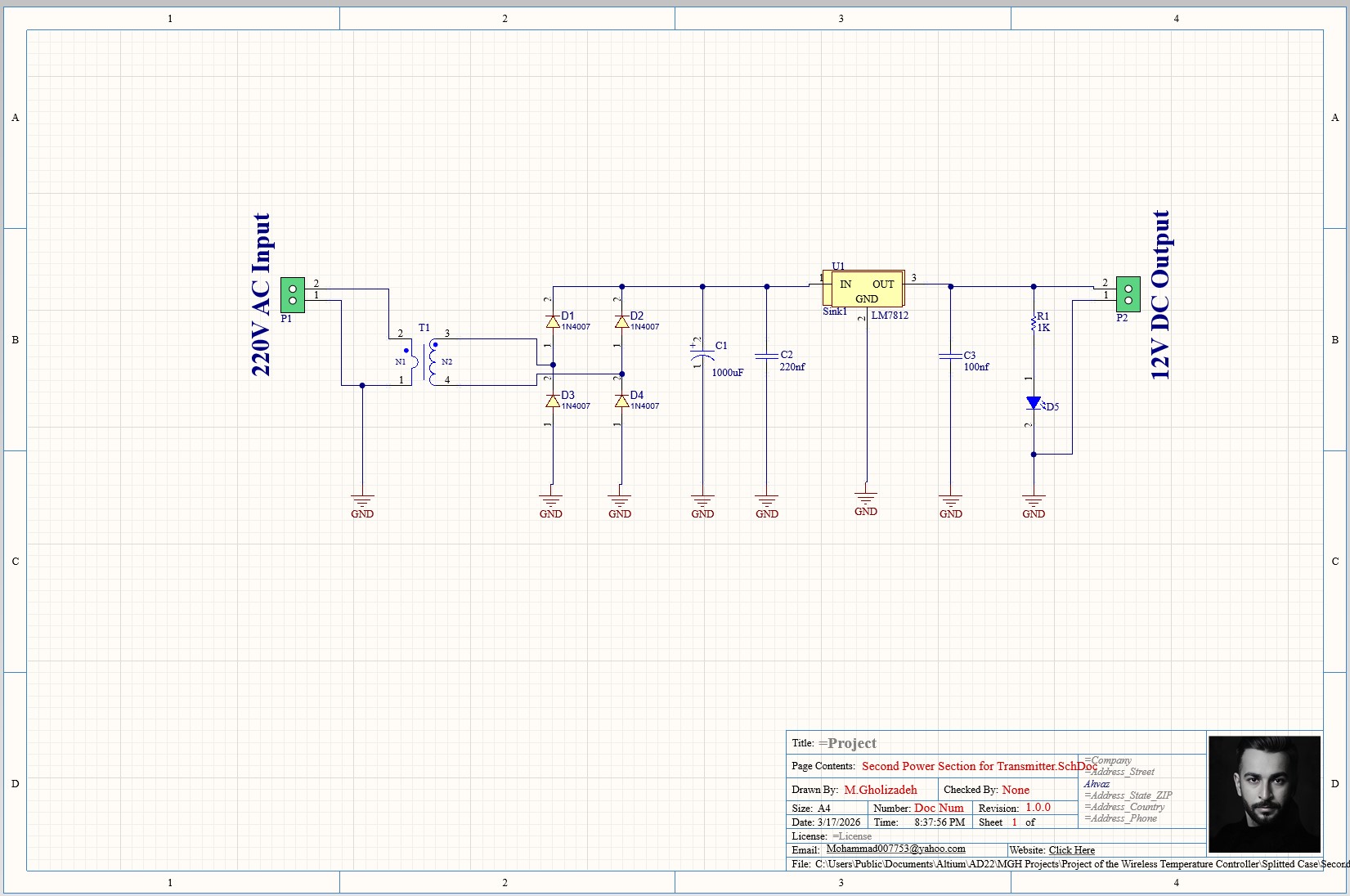
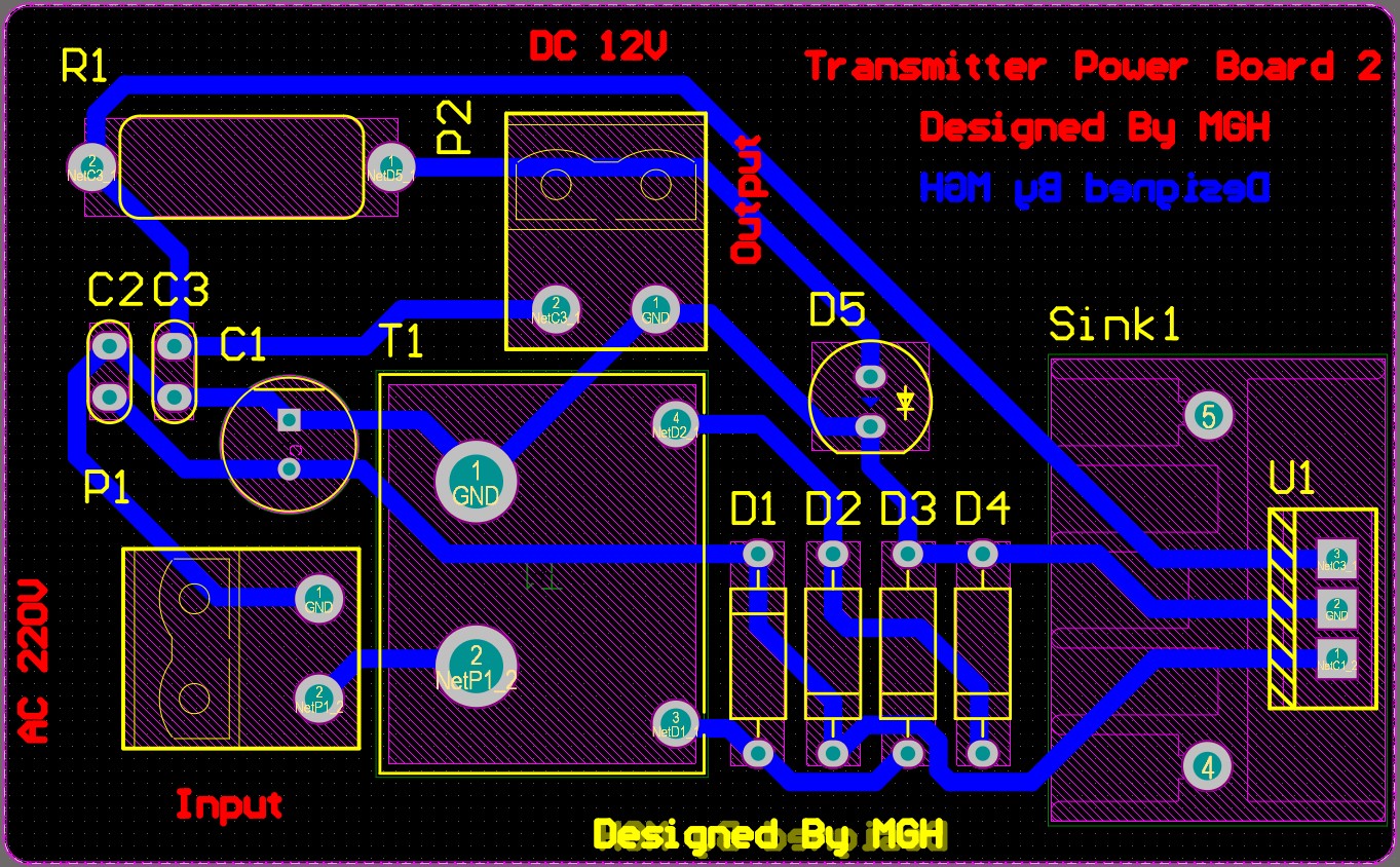
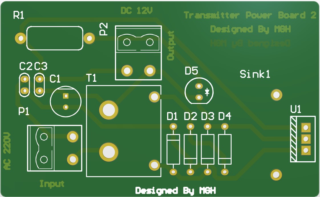
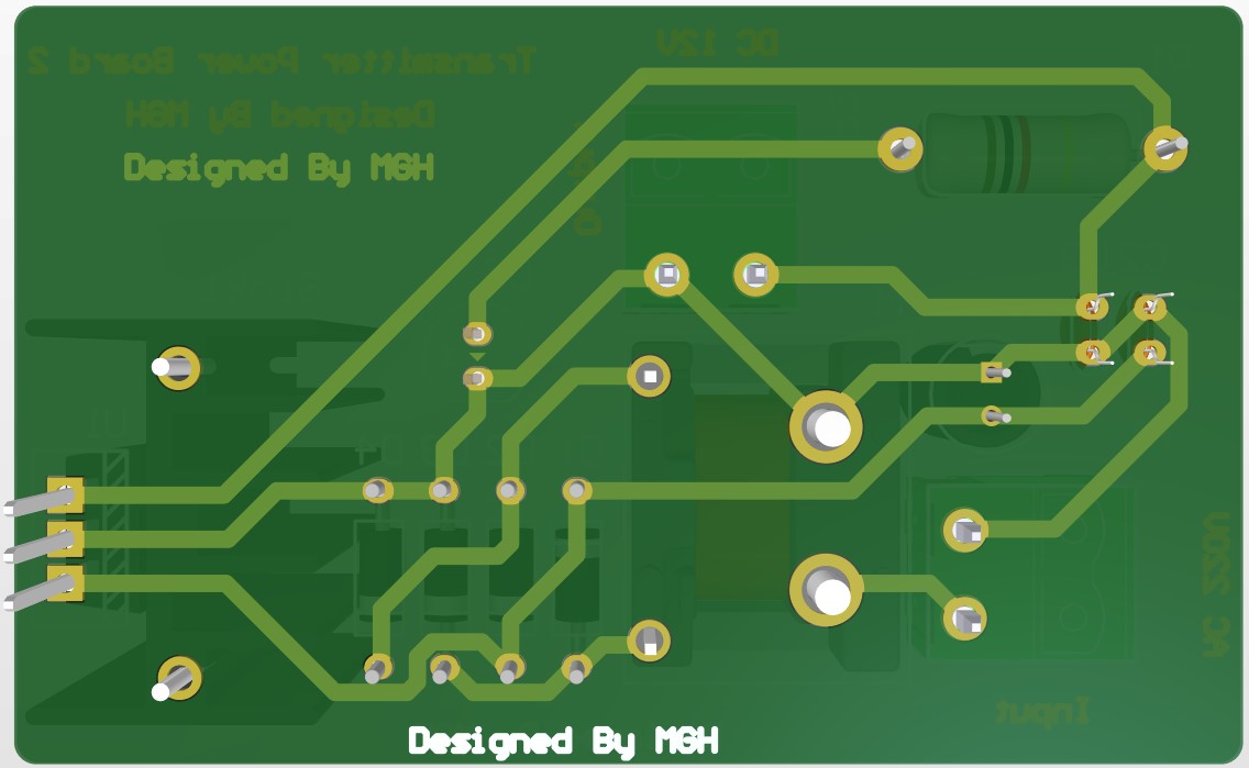
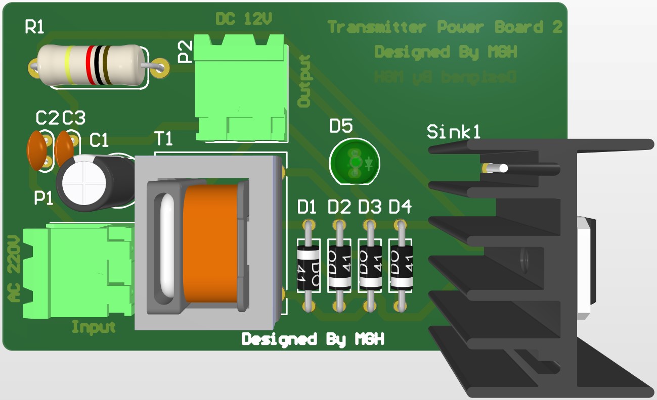
The BOM of the Second Transmitter Power Supply Section can be downloaded by clicking here
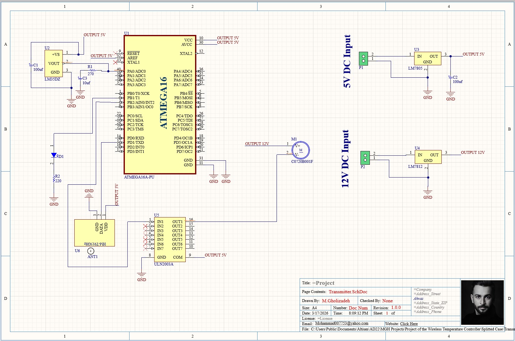
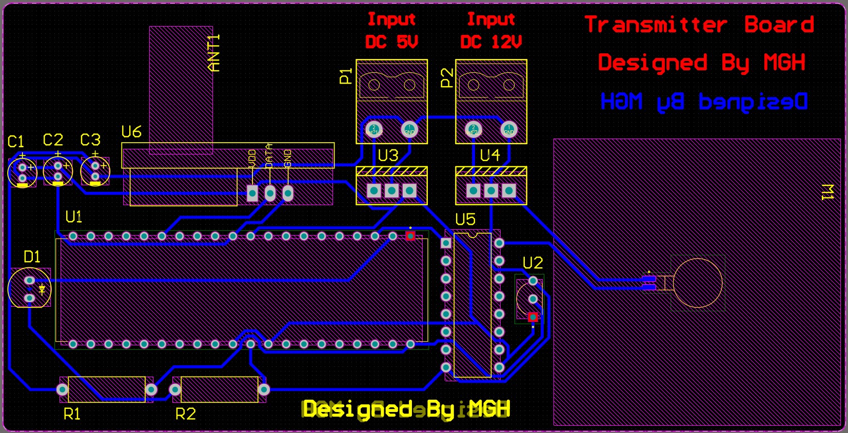
The BOM of the Transmitter Section can be downloaded by clicking here
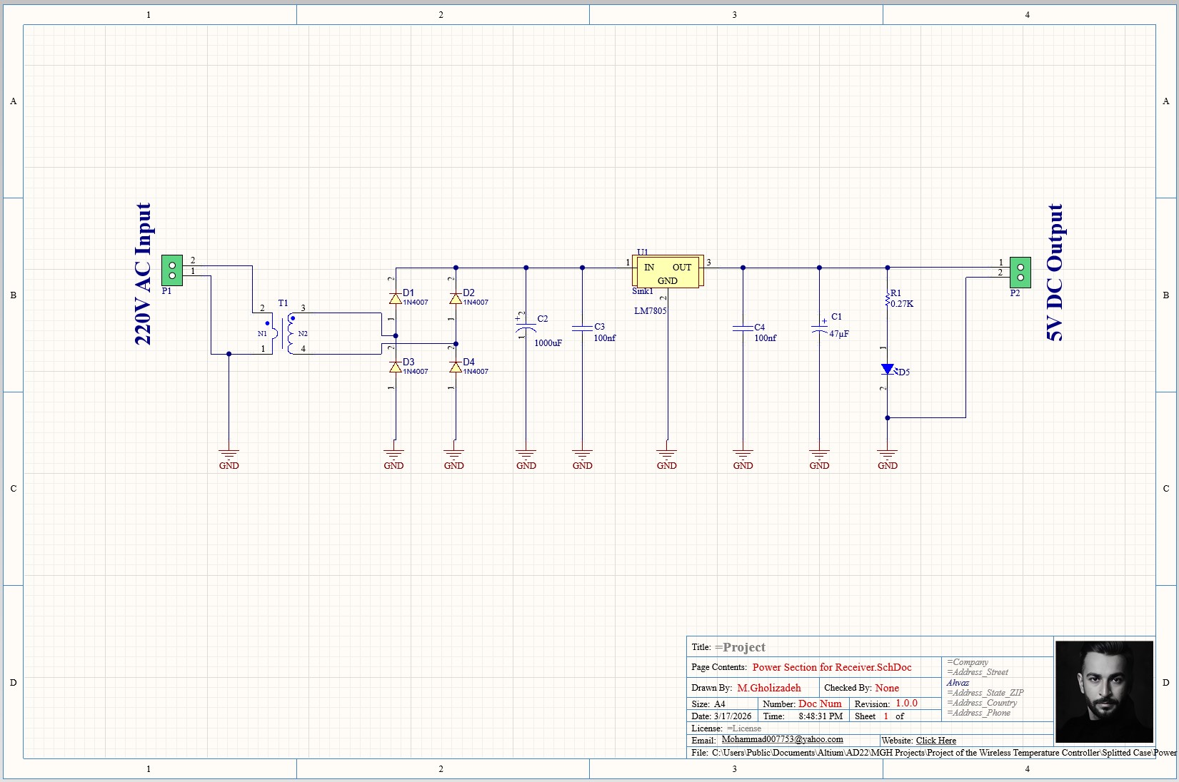
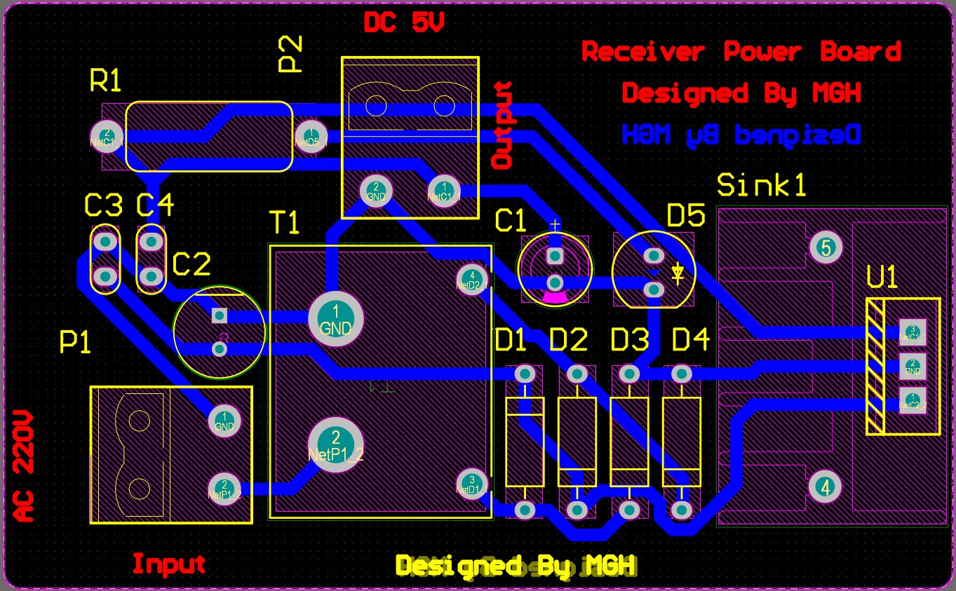
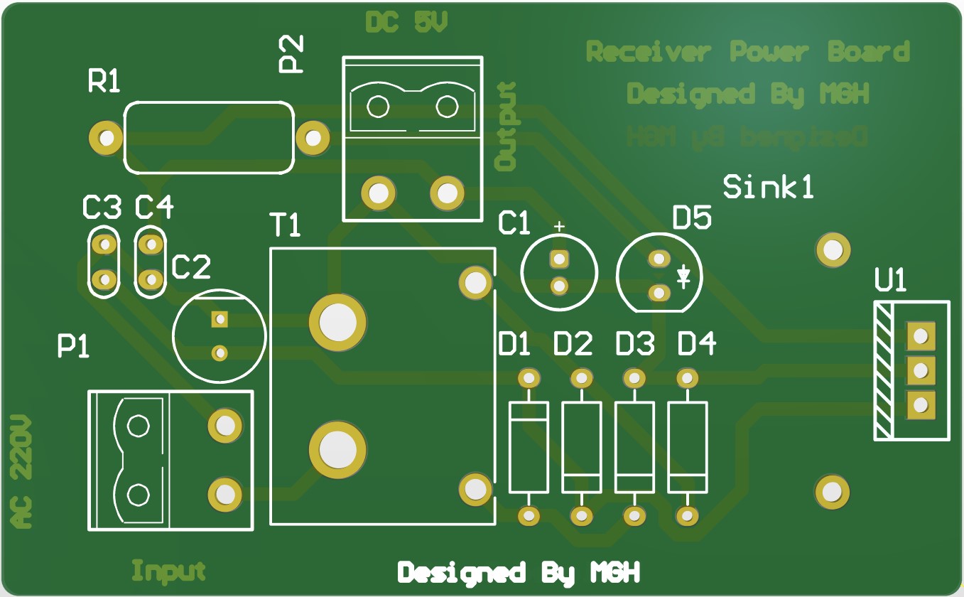
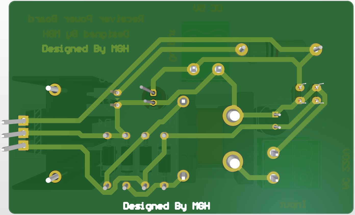
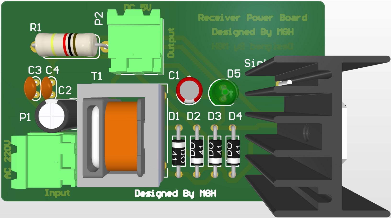
The BOM of the Power Supply Section for the Receiver can be downloaded by clicking here
The BOM of the Receiver can be downloaded by clicking here
Finally, pictures of the device and a clip of how it works are given below: